
In the following we are giving a brief outline, which we try to make suitable also for the non-expert reader, about the technology and physical principles underlying the SLAM-DAST project sensor system, which is based on both stimulated Brillouin scattering effects as well as Rayleigh scattering along single-mode optical fibers, and exploits two techniques in the interrogating equipment for strain and acoustic sensing respectively: Brillouin optical time-domain analyisis (BOTDA) and phase optical time domain reflectometry (φ-OTDR).

Distributed optical fiber sensors (DOFS)
In general terms, distributed optical fiber sensors such as BOTDA and φ-OTDR consist of a sensing fibre cable, which is installed or displaced along the asset to be monitored, and a sensor interrogator equipment that creates the “virtual sensor” that is swept along the cable to measure the distribution of strain, temperature of acoustic deformation along its whole length.
BOTDA sensing
Brillouin optical time domain analysis is based on the stimulated Brillouin scattering effect, which involves an interaction between lightwaves and mechanical vibrations in which the striction induced by the electrical field of the lightwave excites mechanical waves (phonons) inside the fibre at the expense of the wavelength of the light that is interacting[1], with a linear dependence from the temperature and strain in the fibre. By analysing the wavelength of the Brillouin scattered light point-by-point along the fibre, the deformation or temperature is continuously measured just as if a “virtual” sensor would have been swept along the whole fibre length[2].
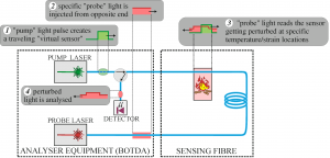
Figure 1: Basic working principle of a Brillouin Optical Time-Domain Analyser (BOTDA): the sensing point moves along the fiber in time according to the time-of-flight of the pump pulse and probe light, and the local strain/temperature measurement is done by sweeping the wavelength shift of the probe light until the maximum perturbation is detected.
The basic working scheme of a BOTDA is presented in Figure 1 and works as follows: (1) a pulse of “pump” light is injected at a first end of the sensing fibre and creates a travelling virtual sensor that moves along its length, while at the opposite end of the fibre (2) the “probe” light having a specific wavelength is continuously injected. When the “travelling” sensor (3) sweeps a region of the sensor that has the temperature (or strain) characteristics tested by the specific “probe” wavelength in use, the probe light results perturbed by stimulated Brillouin amplification. Perturbed light (4) is then analysed in the time-domain in order to locate the position and length of the perturbed region along the sensor.
φ-OTDR
φ-OTDR, on the other hand, is based on the Rayleigh backscattering effect, a linear process in which part of the light injected into an optical fiber is reflected back by random inhomogeneities in the refractive index with a fixed phase relation with the original source. When a probe pulse is sent inside the sensing fiber, the backscattered light reaching the detector at any one time originated from all the scattering centers in a specific section of the fiber occupied by the probe pulse, and thus is the sum of their electric fields which all have a random but stable phase relationship with each other. When the relative positions of these scattering centers changes due to strain or acoustic vibrations, their relative phase relationship changes, thus changing the phase relationship between the backscattered signal and the original probe. By measuring this phase change, it is possible to extract information about fast variation in the strain of every section of the sensing fiber, allowing for detection of acoustic vibrations.
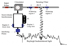
Figure 2: φ-OTDR Interrogator system example, image taken from [3]
An example of a φ-OTDR scheme [3] is shown in Figure 2: the probe pulse is injected at one end of the sensing fiber through an optical circulator. The backscattered light passes through that same circulator and exits in the lower branch, where it enters an interferometer with a path mismatch of ΔL between the two arms. As a result, the detector receives the interference between the light backscatters from two adjacent points in the fiber, and by monitoring this interference pattern it is possible to recover the step by step phase changes of the backscattered light, which in turn are linearly correlated to small strain changes, thus allowing to monitor acoustic vibrations of the sensing fiber.
[1] Brillouin, L., Diffusion de la Lumière et des Rayonnes X par un Corps Transparent Homogéne; Influence del’Agitation Thermique, Annales des Physique, 17, pp. 88-122 (1922).
[2] Horiguchi, T. et al., Tensile Strain Dependence of Brillouin Frequency Shift in Silica Optical Fibers, IEEE Photonics Technology Letters, 1[5], pp. 107-108, (1989).
[3] Kirkendall, C.K., R.E. Bartolo, A.B. Tveten, and A. Dandridge, High-Resolution Distributed Fiber Optic Sensing. NRL Review, (NRL/PU/3430-04-471): p. 179-181, (2004)